
Design Features
Design Characteristics
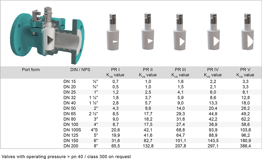
- different KVS values
- individual control characteristics
- free passage possible with open valve
- equal percentage or linear characteristic line
- cost-effective automation
- readily reproducible control position
The construction of the RH-A control valves is based on our standard cavity-free plug valve with chemical resistant PFA/FEP-lining. A wide range of materials for housings, plugs, as well as for sleeves or linings are available for different areas of application. If required, the control valves can also be supplied with a heating jacket.
PT-Diagram
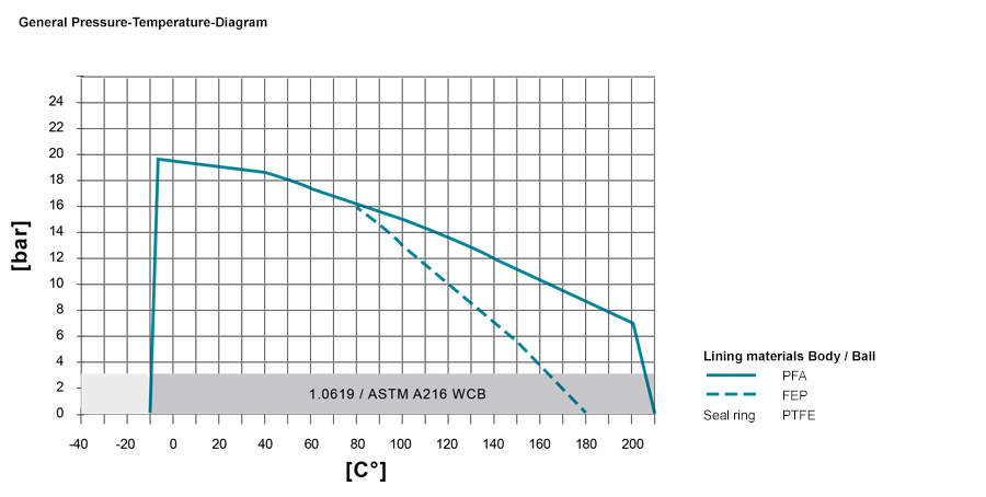
The specified values depend on the respective application (medium). Operating temperatures under -20°C only with body material 1.4408 or low-temperature steel. Hight pressure resistance / temperature resistance on request, e.g. PN 40.
Sleeve: There are different sleeve materials / compounds available.
Materials
Standard body materials
• Ductile cast iron ENJS 1049, ASTM Gr 60-40-18 / A395
Standard plug materials
• Stainless Steel 1.4308, ASTM A351 CF8
Special materials
• Carbon Steel 1.0619, ASTM A216 WCB
• Stainless Steel 1.4408, ASTM A351 CF8M
• Unalloyed stainless steel casting (low Temp.) 1.1138, LCC/LCB/A352
Lining materials
• Body: PFA, PFA-conductive, FEP, PVDF
• Plug: PTFE, PFA, PFA-conductive, FEP, PVDF
Sealing Systems
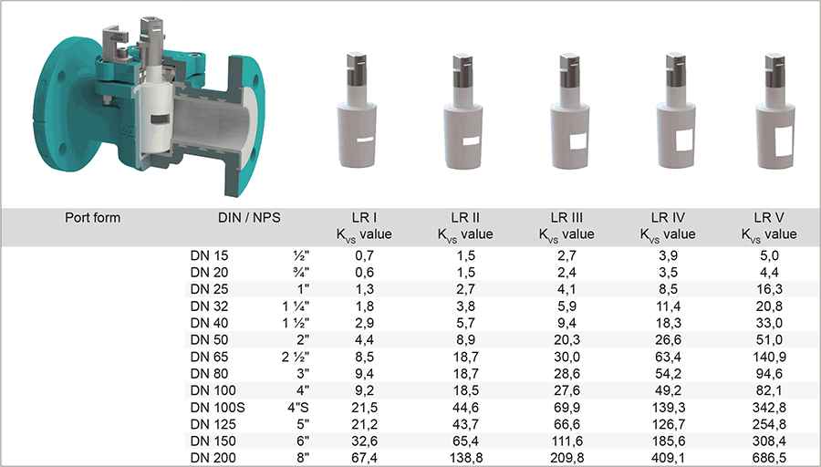
[table id=29 /] [table id=30 /]Port Forms
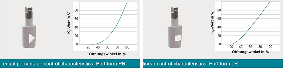
As standard, there are ten plugs forms available per valve size, consisting of five linear and five equal percentage control characteristics.
Furthermore, bespoke plug forms can be calculated and designed according to customer-specific requirements that combine, for example, control properties and free passage.
Characteristics
Type RH-A, linear control characteristics
Type RH, equal percentage control characteristics
Model structure
The data was determined by flow simulation and based on the VDI/VDE 2173 with a permissible deviation of +/- 10% (medium = water 20°C, pressure loss delta p = 1 bar).
Definition Kvs
The KVS value designates the maximum possible throughput for a valve with a 100% opening
Definition Kv
The flow coefficient Kv [m3/h] is a specific volume flow for the following conditions:
– The pressure loss (?p) via the valve is 105 Pa (1 bar)
– The medium is water with a temperature between 278 K and 315 K (5°C to 40°C)
Definition Cv
The flow coefficient Cv is a valve flow coefficient that does not correspond to S.I. units. It represents the number of U.S. gallons of water which flow through a valve with a pressure loss of 1 psi (0.689 mbar) at a temperature of 40°F to 100°F (4°C to 38°C) within a minute. Cv = Kv/0,865
Actuation
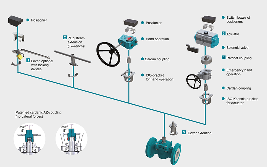
1 Locking Devices
Pilot valve combinations, pad lock eyelets, linear key conception, indexing plunger arrestor.
read more […]
2 Plug stem extension
Solid construction in stainless steel with T-wrench, Standard extension 100 mm or 150 mm, non standard lengths are available on request
read more […]
3 Actuators
Actuators for mounting-flange acc. to DIN ISO 5211
read more […]
NEW: Pneumatic actuator AIR GEAR for plug valves with high torque =150.000 Nm
read more […]
4 Ratched coupling
To usw on multiport valves with standard 90° actuator for bigger switchpositions than 90°
read more […]
5 Cover extension
Solid construction in stainless steel, Standard extension 100 mm or 150 mm high, non standard lengths are available on request . Hexagonal bolts on adjustment ring freely accessible. Note: Don’t use with sealing FSN/FSN-SL and CASN/CASN-SL
read more […]